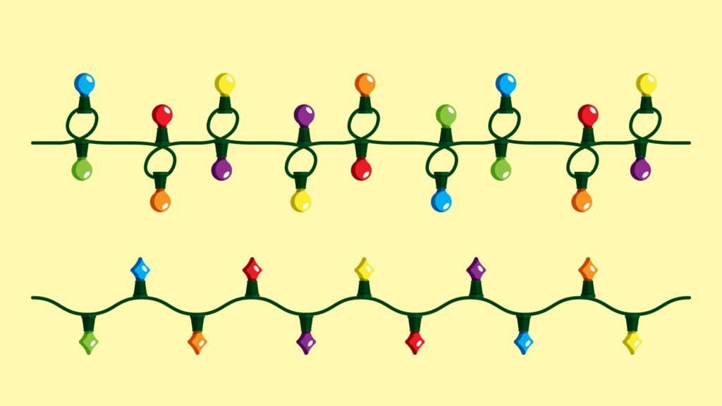
In the following project, we are going to create a circuit where the LEDs are connected in series.
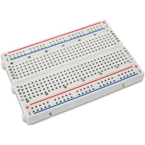
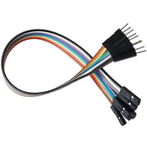
Components Required

Circuit Diagram
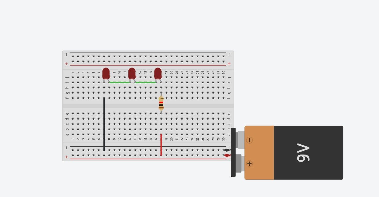
Step-by-Step Guide to Connect the Circuit
Step 1: Get the Power Ready
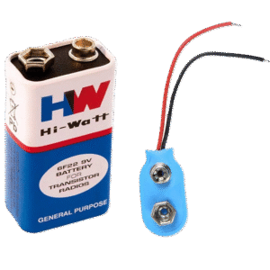
- First, connect the red wire from the battery clip to the long red line on the breadboard. This is the positive (+) side.
- Connect the black wire from the battery clip to the long blue or black line on the breadboard. This is the negative (-) side.
Step 2: Place the Lights
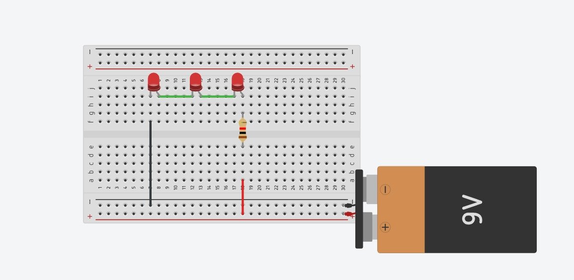
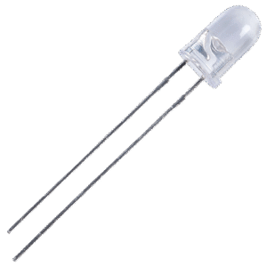
Now for the little LED lights! They have one long leg and one short leg. Make sure you place them just like in the picture.
- Find row numbers on the side of the board.
- Plug the first LED into rows 7 and 8.
- Plug the second LED into rows 12 and 13.
- Plug the third LED into rows 17 and 18.
Step 3: Add the Resistors
- Plug the resistor in row 18 as shown in the diagram.
Step 4: Connect the Wires
- Plug one end of the wire into the negative (-) line and the other end into row 8.
- Plug one end of the wire into the positive (+) line and the other end into row 18.
Output